The Model Settings may be accessed through the menu or toolbar buttons highlighted below.
The Model Settings are settings specific to the model which is currently open. The information stored here is retained with the model, and will be retained even if the model is opened on a different computer.
You may save any of the settings in the Model Settings as the default setting, such that new models you create will begin with the settings that you saved as Defaults. To do this, simply enter the information that you want to save and click the Save as Defaults button.
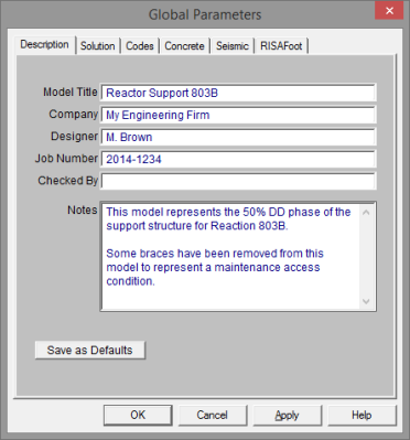
The entries under the Description tab are used to enter descriptive information such as a title for the particular model being defined, the name of the designer and a job number. The title may then be printed at the top of each sheet of the output, and on the graphic printouts of the model. Note that for any of these tabs, you can click on Save as Defaults and then your settings will be saved the next time you open the program.
The Checked By field is intended for the model reviewer to initial upon completion of a model review. Their initials will then be printed on each sheet of the output.
The Notes field is intended for information about the model that may be useful for the engineer or reviewer to refer to.
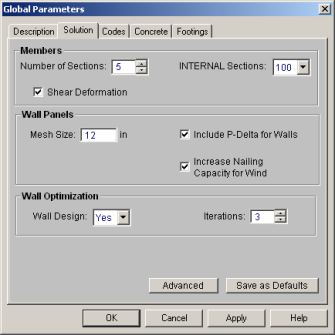
The entries under the Solution tab are used to control settings that affect the general solution of the model.
Number of Sections controls
how many places you receive reported
Number of Internal
Sections controls how many places along each
Note:
Check the Shear Deformation box if shear deformation considerations are to be included in the model solution. See Member Shear Deformations for more information.
The Mesh Size is the base mesh size that is used when wall panels solved. If there is a constraint smaller than this mesh size, the mesh will be refined to accommodate this constraint. You can see the mesh size graphically on the wall panels when you solve your model.
Note: The mesh size is also used for plate sub-mesh for RISAFloor Concrete floor Semi-Rigid diaphragms.
Include P-Delta for Walls is used to enable P-Delta analysis for wall panels. Even if this box is checked the P-Delta analysis will only be performed on load combinations which have P-Delta enabled.
The Increase Nailing Capacity for Wind option will automatically increase the shear capacity of wood wall and diaphragm panels by 1.4 for all load combinations that contain wind loads. Load combinations that have both wind and seismic loads acting simultaneously will not receive this increase.
The Wall Design option defines whether you want to automatically iterate the solution for masonry and wood walls.
The Iterations option defines how many automatic iterations will occur.
Note:
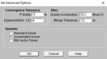
The P-Delta Tolerance is used to adjust the tolerance used to determine convergence of the P-Delta analysis. Be sure to enter this value as a percentage! The default for this is ½ of 1 percent (.5%). See P-Delta Analysis to learn more about this.
The Convergence Tolerance is used to set how close a subsequent solution must be to the previous solution for a mode to be considered converged. See Dynamic Analysis for more information.
The Gravity Acceleration is used to convert loads into masses for the purpose of a dynamic analysis.
The Merge Tolerance is used as the maximum
distance 2 joints
can be apart and still be merged together. It is also used when
scanning for crossing members and for unattached joints along the spans
of
The Dynamics Solver options allow you to choose between the Standard Solver, the Accelerated Solver and a Ritz Vector solution. Refer to the Solution topic for a more details.
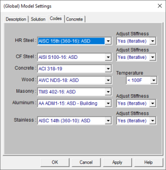
The settings under the Codes tab control which design code is used for code checks for each material type.
The HR Steel entry indicates which code is to be used for the design of hot rolled steel. For more information see Hot Rolled Steel Design.
Note:
The CF Steel entry indicates which steel code is to be used for the design of cold formed steel. For more information see Cold Formed Steel Design.
The Wood entry indicates which wood code is to be used for the design of wood, including wood walls and structural composite lumber. For more information see Wood Design.
Note:
The Concrete entry indicates which concrete code is to be used in the design of concrete members and walls. For more information see Concrete Design.
Note:
The Masonry entry indicates which masonry code is to be used for the design of masonry walls. For more information see Masonry Design.
Note:
_348x283.jpg)
The entries under the Concrete tab contain options related to
the analysis and design of concrete
The Shear Tie Options allow you to control the Number of Shear
Regions that will be used when detailing
a beam
The Concrete Stress Options allow you to choose what type of stress block to consider in your analysis. The options are the constant Rectangular Stress Block and the Parabolic Stress Block. See Parabolic vs. Rectangular Stress Blocks for more information.
Check the Used Cracked Sections box if you want to modify the member and wall stiffnesses by the Icr Factor as described in both the Concrete - Design and Wall Panels topics.
Check the
Checking the Minimum 1 Bar Dia Spacing box will allow a minimum spacing of one bar diameter between parallel bars. Otherwise, RISA will default to a two bar diameter or one inch clear spacing, whichever is greater, to allow for lap splices and continue to maintain adequate spacing between parallel bars.
The Concrete Rebar Set allows you to choose from the standard ASTM A615 (imperial), ASTM A615M ("hard" metric, i.e. #8M is an 8mm bar), prENV 10080 (Euro), CSA G30.18 (Canadian), and AS/NZS 4671:2001 (Australian/New Zealand) reinforcement standards.
The Include Welded Wire Reinf. (ASTMA1064) in Slab Design allows you to design a slab using Welded Wire Reinforcement.
Note:
Users shall choose the correct material in the Materials Spreadsheet to account for ASTM A1064 steel.
Welded wire reinforcement is only available for
Only ASTM A1064 deformed bar sizes are available.
The Minimum % Steel for Columns allows you to choose the minimum percentage of reinforcement steel to be used in a concrete column section. The percentage entered will be multiplied by the gross area of the column section to determine the minimum amount of reinforcement required in each column. It should be noted that the minimum percentage allowed by ACI 318-14 Section 10.6.1.1 (ACI 318-11 Section 10.9.1) is 1%.
The Maximum % Steel for Columns allows you to choose the maximum percentage of reinforcement steel to be used in a concrete column section. The percentage entered will be multiplied by the gross area of the column section to determine the maximum amount of reinforcement allowed in each column. It should be noted that the maximum percentage allowed by ACI 318-14 Section 10.6.1.1 (ACI 318-11 Section 10.9.1)1 is 8%.
The Elevated Slab Design Option is only visible when you have elevated slabs. This option offers a choice between two methods, namely the Construction method and the Theoretical method, for the design of the slab rebar. The Construction method, which is the default method employed by the program for a significant period, determines the design of the slab based on an integer number of rebar. This method operates under the assumption that if the strip width divided by rebar spacing is not an integer, an additional rebar will be provided to guarantee the presence of a rebar at each end of the design strip. On the other hand, the Theoretical method is a new method added later that enables the program to calculate the rebar area based on the average value, where the rebar area equals As (single rebar) multiplied by the Strip Width divided by Spacing. However, it is crucial to note that this method may not always result in an integer number of rebar so unlike the Construction method, the results for Theoretical method will have no info of rebar amount.
Note:
Concrete cover for beams and columns is specified under Design Rules under the Concrete Rebar tab.